WHITE PAPERS
from the files of
Networking Unlimited, Inc.
Configuration for Transparently Redundant Firewalls
Dr. Vincent C. Jones, PE
WhitePapers@NetworkingUnlimited.com
Version 1.02 -- 25 May 2001
Firewalls play a critical role in modern networks, and their importance is increasing as organizations recognize the vulnerabilities of internetworking. We can no longer be satisfied merely to have accomplished communications. The ability to communicate is now a given and the challenge is to do so safely and efficiently. It is possible and practical to configure redundant firewalls to provide continued operation despite router, access network, or firewall failure and this white paper illustrates one way that it can be done with no dependence on proprietary firewall or router capabilities. Impact on security is minimal because the only communications between inside and outside routers is through the firewalls and the only information trusted is whether or not a particular firewall can be used to reach a particular router on the other side. The firewalls do not exchange routing information with or otherwise trust any routers, and can continue to run in a conservative, secure configuration using network address translation, arbitrary state-sensitive filters, proxies, and static routing. An example configuration for Cisco routers is provided.
Background
Any time we have a connection between networks with differing security policies, we need to provide protection. Firewalls can provide enforcement of security policies between networks, simplifying and strengthening the access controls already in place on services and user systems. For example, a firewall may be configured to allow only web requests to get to the web server, only DNS requests to get to the domain name server, and yet let inside users access outside resources unhindered. That way, the web administrators can devote their time to strengthening the web services rather than protecting services not provided to the outside network.
There are many styles of firewall operation, from simple address and socket filters to transparent proxies, and many conflicting claims as to which is better in terms of providing higher security or superior user transparency. But from the viewpoint of the network design, all we care about is whether or not the path through the firewall is state sensitive and whether the firewall appears to our routers as an end-system or as another router.
The former distinction is usually referred to as static versus dynamic filtering. The latter distinction is usually ignored by security experts, as it has no impact on firewall operation or effectiveness. It does, however, have considerable impact on the design of the networks supporting the firewalls, as will be seen in our configuration examples. Since there is no formal lexicon to describe the two modes, we will refer to them here as router mode and end-system mode.
In a static filter, each packet is independently evaluated, with no reference to any preceding packets which may have passed in either direction. A static filter may also be referred to as a static NAT or a passive screening firewall. The technique developed in this white paper can provide full transparent redundancy and load sharing through firewalls which use static filtering.
In a dynamic filter, the decision on whether or not to pass a packet will depend upon what packets have already been through the firewall. Examples of dynamic filters are stateful inspection and proxies. These filters monitor the exchange of packets, effectively opening holes in the firewall for each connection on an as needed basis, such as when an inside user places a request for service, and then close the holes created as soon as they are no longer needed for authorized traffic.
Transparent proxies depend heavily on dynamic filtering so that protocols like FTP can work through the firewall without diminishing overall security. Our challenge with dynamic firewalls is that the correct behavior of the firewall depends upon the state of the firewall and transparent redundancy is not possible unless the firewall can share that state information with its backup unit. This limits our ability to provide transparent redundancy for dynamic filtering firewalls to those which include proprietary synchronization mechanisms. If there is no synchronization of the dynamic filters, we can automate the failover to a backup firewall but all open communications requiring state information for continuity will be dropped and need to be reestablished through the replacement firewall before continuing.
When using dynamic filtering firewalls, we must insure that our routing schemes always route packets between any communicating pair of users crossing a firewall boundary through the same firewall in both directions. Otherwise, the filter opened based on the inside connection request might not be on the firewall used to return the response back from the outside system. To minimize service disruptions, this firewall selection must be maintained despite failures in supporting routers or connected networks.
Router Mode versus End-System Mode Firewalls
The distinction between router mode and end-system mode has a major impact on a redundant firewall network design. This may come as a surprise, given that the impact on a conventional network is so minimal the distinction is usually ignored by the firewall specialist. Indeed, router mode versus end-system mode is often confused with proxy-mode versus pass-through mode considerations, which can impact security but have no impact on network design.
End-system mode firewall usage is compatible with any addressing scheme on either network because neither the inside nor the outside network have any visibility into the existence of the other network. There is no need for the IP addresses used on either side of the firewall to be unique. This allows the firewall to effectively link networks with overlapping address space, a common requirement when communicating between two organizations using RFC 1918 private addresses. As long as there is address space in each network to be used by its side of the firewall and the application being supported uses a protocol the firewall knows how to proxy (or one that does not need to be proxied because no addressing information is carried as part of the protocol payload), communications can proceed safely and securely.
When running in router mode, the routing which was automatic in end-system mode must now be performed manually. Since there is no IP subnetwork containing the IP addresses used for destinations on the other side of the firewall, we need to distribute knowledge of the correct path to use throughout the inside network. In a small network, we might include a static route on every inside router. In larger networks, this quickly becomes impractical and we will usually configure the firewall access routers to redistribute the appropriate static routes into their routing domain.
Our challenge is that we can only configure our routers to provide automatic protection against firewall failures when the firewalls can be treated by the routers as routers. The problem is that we cannot support two end-systems with the same IP address (which is what would be required for one end-system mode firewall to duplicate a specific service provided by another end-system mode firewall). When the firewalls are using router mode, there is no problem because having multiple IP addresses defined as a route to a single IP address is just business as usual.
Since there are some environments where the choice of running the firewalls in router mode is not available, we will discuss how to provide automatic failover for firewalls in end-system mode as well as those in router mode. But be forewarned that the solution is not pretty, as we must use multiple tricks to make firewalls appear to our routers as router-mode firewalls even though they are not, and then NAT the addresses used by the firewalls to present a consistent address appearance to the users. While it can be done, the resultant configurations are much more complex and place strict constraints on address assignments.
Router Controlled Failover Using Mirrored Router Mode Firewalls
The most common use of router-mode firewalls, where the address
of the firewall and the address of the destination on the other
side of the firewall are independent, is to support general purpose
Internet access, so we will implement a configuration to support the
scenario in Figure 1. While we show only a single web server being
accessed from a single user on the Internet, the solution is easily
scaled to support access in both directions and as many systems as the
firewalls can handle. We just need to keep in mind that while in normal
operations we may be able to split the load across both firewalls,
we must size the firewalls to be able to continue operations with
adequate performance when just one of the two is functional.
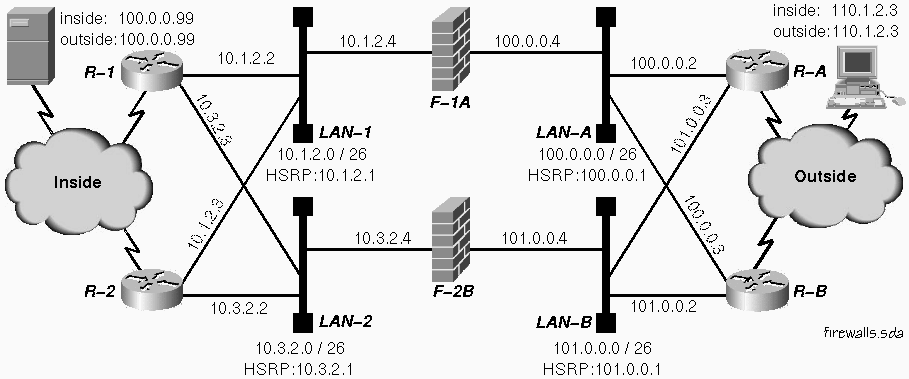
Figure 1: Redundant routers with redundant firewalls.
The firewalls in this example are assumed to be configured identically in terms of the user services provided. That means that all addresses used for network address translation or proxy access are independent of the addresses used to identify the physical ports on the firewall. From the viewpoint of network operations, the security policy implemented on the firewalls and the mechanisms used to enforce security are irrelevant.
For this example, we assume each firewall will pass any legitimate web traffic between any valid Internet address and our web server at 100.0.0.99. On this network, we route to the public address of the web server and establish a default route that takes us back out to the outside world via a firewall. This mode of operation for the ``inside'' network is typical for a DMZ network.
Note that we need to configure the routing so that any specific user's requests and the responses to those requests will always be delivered to the same firewall. Otherwise any state information associated with existing connections will be unavailable and browsing may be disrupted. While this service disruption is considered acceptable if the alternative is no service, as when switching firewalls to recover from a firewall or access LAN failure, it is not something we want as part of normal operation.
The key to recovering from firewall failure is our use of BGP to detect
when a path through a firewall is available. By advertising a unique
target address for each available path, we can trigger the appropriate
floating static route to direct our production traffic. To provide
protection against as many double faults as possible, we define the
four paths in Table 1. Keep in mind that failure of any access LAN
is equivalent to failure of the firewall served by that LAN.
|
Path |
Inside Router |
Firewall and LANs |
Outside Router |
|---|---|---|---|
|
1 |
Router R-1 |
LAN-1 <=> Firewall F-1A <=> LAN-A |
Router R-A |
|
2 |
Router R-1 |
LAN-2 <=> Firewall F-2B <=> LAN-B |
Router R-B |
|
3 |
Router R-2 |
LAN-1 <=> Firewall F-1A <=> LAN-A |
Router R-B |
|
4 |
Router R-2 |
LAN-2 <=> Firewall F-2B <=> LAN-B |
Router R-A |
Table 1: Path selection for maximum double fault tolerance using four paths.
The critical concept behind our design is that rather than using static routes pointing to a specific firewall service address to direct incoming and outgoing traffic to the appropriate firewall (and nowhere else), we instead use floating static routes that point to loopback interface addresses on the other side of the firewalls that we learn via BGP. When a path fails, the target address associated with that path becomes unreachable and a backup route using a different path will float into action. By careful selection of the route weights and sharing of local route information between routers, we minimize the potential for unnecessary changing of firewalls for any traffic flow.
The definition of the firewall conduits for exchanging BGP routing
information which are the key to automating firewall failover are
specified in Table 2. Note that we only need to provide a conduit
for the BGP speaker on the inside to contact the BGP speaker on the
outside. If the BGP speakers on the outside routers do not support
a passive (listen only) option, this will cause false alarms during
connection setup as the outside BGP speakers attempt to connect to
their neighbors on the inside. The connection attempts will stop as
soon as the inside speaker establishes a connection to the outside
speaker, but could be annoying if an inside speaker fails.
|
Service |
Configuration |
|---|---|
|
BGP Conduit for R-1 with R-A via |
10.1.2.2 NAT to 100.0.0.65 |
|
BGP Conduit for R-1 with R-B via |
10.3.2.3 NAT to 101.0.0.65 |
|
BGP Conduit for R-2 with R-B via |
10.1.2.3 NAT to 100.0.0.66 |
|
BGP Conduit for R-2 with R-A via |
10.3.2.2 NAT to 101.0.0.66 |
Table 2: Firewall configuration for BGP redundancy support
We define two target addresses on each of the four routers, one for
each path to that router using the assignments in Table 3. We use
address filters on our BGP advertisements to allow only the correct
targets to be learned over each peering associated with any path.
|
Path |
Inside Router |
Firewall |
Outside Router |
|---|---|---|---|
|
R-1 <=> F-1A <=> R-A |
10.255.255.1 |
Firewall F-1A |
10.255.255.11 |
|
R-1 <=> F-2B <=> R-B |
10.255.255.2 |
Firewall F-2B |
10.255.255.13 |
|
R-2 <=> F-1A <=> R-B |
10.255.255.3 |
Firewall F-1A |
10.255.255.14 |
|
R-2 <=> F-2B <=> R-A |
10.255.255.4 |
Firewall F-2B |
10.255.255.12 |
Table 3: Target addresses for each path from each router.
We then define our floating static routes so that traffic to and from the DMZ web server will always use path 1 or 3 if available and only use path 2 or 4 if there is no other choice. Note that in order for failure recovery to work, it is essential that the only way that the routers can learn a route to any of the target addresses on the other side of the firewall be through BGP.
Since BGP includes the address of the next hop to take as part of the route advertisement, we will also need to configure our BGP speakers to override that address with the correct address for the firewall. The specific technique used will depend upon the BGP implementation. For the example configurations which follow using Cisco routers we use route-maps. If we were using the Merit GateD routing daemon for Unix and Linux, we would instead configure a gateway address as part of the peer definition. The critical requirement is that we do not believe the next hop specified by the router on the other side of the firewall, as to do so would severely degrade the security protection provided by the firewalls.
Inside Router Configuration
WARNING: Router configuration details for self defense, network management, and to reinforce firewall restrictions (for redundant security protection) are not shown in order to focus on the firewall failover capability. In a real world implementation, particularly one connecting to the Internet, neglecting router security can be expected to have a severe negative impact on availability.
Listing 1 shows the essential parts of the configuration of router R-1. We set up our static routes so that Firewall F-1A is the preferred path to the general outside world, directly from this router if the BGP path through Firewall F-1A is up, otherwise with an extra hop via Router R-2 if its BGP path through Firewall F-1A is up. Only if neither inside router has a path via Firewall F-1A will we fall back to a path through Firewall F-2B.
version 11.2
!
hostname R-1
!
ip subnet-zero
!
interface Loopback0
description Management ID for this Router
ip address 10.0.0.101 255.255.255.255
!
interface Loopback1
description Target address for outside to inside via Firewall F-1A
ip address 10.255.255.1 255.255.255.255
!
interface Loopback2
description Target address for outside to inside via Firewall F-2B
ip address 10.255.255.2 255.255.255.255
!
interface Ethernet0
description Firewall Access LAN-1
ip address 10.1.2.2 255.255.255.192
no ip redirects
standby 1 priority 200
standby 1 preempt
standby 1 ip 10.1.2.1
!
interface Ethernet1
description Firewall Access LAN-2
ip address 10.3.2.3 255.255.255.192
no ip redirects
standby 2 priority 100
standby 2 ip 10.3.2.1
!
router ospf 123
network 10.0.0.101 0.0.0.0 area 59
network 10.1.2.0 0.0.0.63 area 59
network 10.3.2.0 0.0.0.63 area 59
! . . . network definitions for other interfaces go here
default-information originate
!
router bgp 65111
no synchronization
network 10.255.255.1 mask 255.255.255.255
network 10.255.255.2 mask 255.255.255.255
neighbor 10.0.0.102 remote-as 65111
neighbor 10.0.0.102 description IBGP with R-2
neighbor 10.0.0.102 update-source Loopback0
neighbor 10.0.0.102 route-map map_here out
neighbor 10.1.2.65 remote-as 60000
neighbor 10.1.2.65 description Peering with R-A via F-1A (10.255.255.11)
neighbor 10.1.2.65 ebgp-multihop
neighbor 10.1.2.65 distribute-list 11 in
neighbor 10.1.2.65 distribute-list 1 out
neighbor 10.1.2.65 route-map map_hop_11 in
neighbor 10.3.2.66 remote-as 60000
neighbor 10.3.2.66 description Peering with R-B via F-2B (10.255.255.13)
neighbor 10.3.2.66 ebgp-multihop
neighbor 10.3.2.66 distribute-list 13 in
neighbor 10.3.2.66 distribute-list 2 out
neighbor 10.3.2.66 route-map map_hop_13 in
!
ip classless
ip route 0.0.0.0 0.0.0.0 10.255.255.11 1 ! Direct to F-1A
ip route 0.0.0.0 0.0.0.0 10.255.255.14 2 ! To F-1A via R-2
ip route 0.0.0.0 0.0.0.0 10.255.255.13 3 ! Direct to F-2B
ip route 0.0.0.0 0.0.0.0 10.255.255.12 4 ! To F-2B via R-2
ip route 10.1.2.65 255.255.255.255 10.1.2.4 ! To R-A via F-1A
ip route 10.3.2.66 255.255.255.255 10.3.2.4 ! To R-B via F-2B
!
access-list 1 permit 10.255.255.1
access-list 2 permit 10.255.255.2
access-list 11 permit 10.255.255.11
access-list 13 permit 10.255.255.13
access-list 20 permit 10.255.255.11
access-list 20 permit 10.255.255.13
!
route-map map_here permit 10
match ip address 20
set ip next-hop 10.0.0.101
!
route-map map_hop_11 permit 10
match address 11
set ip next-hop 10.1.2.4
!
route-map map_hop_13 permit 10
match address 13
set ip next-hop 10.3.2.4
!
end
Listing 1: Inside Router R-1 Configuration for Redundant Firewall
Failover
Interface Loopback0 is a standard host IP definition for the router to provide a constant IP address independent of the state of any real interfaces. We use this address for the IBGP peering between the two inside routers used to share reachability of the outside routers via the firewalls.
There is no benefit to distributing the external or internal target addresses defined by interface Loopback1 and 2 (all addresses in this configuration starting with prefix 10.255.255) into OSPF (or whatever intradomain routing protocol we choose to use) as there should never be any traffic to or from those IP addresses. We do need to share any outside target addresses we can reach with Router R-2, but that will occur as a result of the IBGP session we set up between routers R-1 and R-2.
The access LAN interfaces are a standard configuration and are unaffected by our adding support for firewall failover. We use HSRP to make this router the preferred default gateway for Firewall F-1A and the backup default gateway for Firewall F-2B. We do not show any interfaces configured to support local users, but if there are any local access requirements, we would put them on their own LANs and not compromise our security by sharing the firewall access LANs (unless allowed by our security policy).
We show OSPF as the inside routing protocol, and configure it to distribute the access LANs and the management loopback address. This ensures that the two inside access routers can find each other to exchange BGP routing information and to provide paths for each other to reach the firewalls if necessary. When one access router advertises reachability through the firewalls and the other router needs to use that path, we must ensure that the other router routes the packet through the router which has the path rather than directly to the firewall. Otherwise we risk a black hole in our routing if the path is down because of a problem with the access LAN.
The production paths through the firewall are conditionally advertised based on a route through the firewall being available. The default route is redistributed by the default-information originate line.
The key to failure recovery is that when the packet gets to this router, it will use the best static route through the firewalls available for that destination, whether that route is directly to the preferred firewall, indirectly to the preferred firewall via the other access router, or directly or indirectly to the backup firewall for that service. Which of the possible routes are currently available is determined by BGP exchanges between the inside and the outside routers, but the routes themselves are static. Even if an outside router is taken over by hostile forces, it can not cause an inside router to use any path other then one of the four that we have already defined through the firewalls.
In order for the static routes to work correctly, it is essential that the addresses used for targets be unique in the domain of the side using them. If some other inside router were to advertise a route to 10.255.255.11 for example, we could wind up sending data intended for the outside to that location instead.
We also need to define a pair of static routes so that BGP can get to the speakers on the other side of the firewalls. These routes are only used locally on the router and are not advertised by any protocols to other systems.
The key to the failover function is the BGP setup under router bgp 65111. We use EBGP across the firewalls and IBGP between the access routers on each side of the firewalls. This router provides the two targets 10.255.255.1 and 10.255.255.2, so BGP is configured by the two network statements to source only those two routes.
The first peer configured (neighbor 10.0.0.102) is the IBGP peering with the other inside router, Router R-2. This serves dual purposes. First of all, the rules of BGP configuration require all BGP speakers in an Autonomous System to be fully meshed. Second, it allows us to share any routes through the firewalls that we detect with Router R-2 and to learn of any routes Router R-2 has detected from its BGP peerings across the firewalls. This peering has the fringe benefit of allowing us to keep all the artificial addresses used for steering firewall traffic out of the OSPF routing domain.
The next peer (neighbor 10.1.2.65) is the first of our two peers going through the firewalls to an outside router. The static route vectors our packets to this peer to the IP address 10.1.2.4 on Firewall F-1A. The firewall tests the packet for validity, translates the destination address from 10.1.2.65 to the actual address of Router R-A of 100.0.0.2, and changes the source address from our local address of 10.1.2.2 to the IP address of the firewall conduit on the outside of 100.0.0.65. The firewall is not required to understand the BGP protocol and does not need to adjust any of the addresses contained in the data fields of the packet. We will configure BGP to ignore all addresses in the advertisement with the exception of the one target address we expect to learn over this path.
The ebgp-multihop line is required because the remote peer is not on a common subnet with this router.
The next two lines define distribution lists for input and output that limit the BGP session with this peer to only accepting a route to the target address for this path and only shares the one route we want associated with this path on the outside. While this might appear to be overkill, since we will be applying identical filters on the other side of the firewall, we really do want both filters on both sides. We must limit what we accept as we do not trust the other side to never attempt to send us potentially confusing or misleading routes. We limit what we advertise to minimize the information we expose about our internal configuration.
In the last line for this peer, the route map map_hop_11 looks for an address in the incoming updates that matches access-list 11 and sets the next hop value for that address to 10.1.2.4, the firewall port to use for this path through Firewall F-1A. Even if the next hop information provided was the correct IP address for us to use on this side of the firewall (or the firewall understands BGP enough to do the translation for us), we dare not trust it. Just in case the other router has been taken over by evil forces, we do not trust the BGP session through the firewall to tell us anything other than whether or not a particular path between the inside and the outside appears to be functional.
The remainder of the BGP section is the configuration of the BGP peering for the alternate route through the firewalls from this router. This peering is configured the same as the primary route, the only modifications are those required to match the addresses appropriate for this route.
We then define a set of floating static routes with an explicit weighted route for each potential path through the firewalls. These target IP addresses are only reachable when BGP learns of them, at which time the next hop values will be included in the routing table and can be seen using the show ip route command. We set up the default route to use our direct path through Firewall F-1A if available, falling back to the path through the same firewall advertised (and reached) from Router R-2. If there is no path available through Firewall F-1A, we will use a path through Firewall F-2B, again preferring our direct path over the indirect path via Router R-2. If there are no paths available, none of the floating static routes will activate and OSPF will cease to advertise the availability of a default route.
The last two static routes tell BGP how to get to the BGP speakers on the other side of the firewalls.
The first four access lists are used by BGP to control routes advertised and routes accepted. Lists 11 and 13 are also used by the route maps to determine which incoming advertisements need to get their next hop field adjusted. Access list 20 is the logical OR of lists 11 and 13, and is used for the outbound route map map_here.
Router R-2 would use an almost identical configuration, with only minor changes to reflect the address differences. In particular, the Loopback interfaces would have addresses appropriate for this router (targets 10.255.255.3 and 10.255.255.4) and the access LANs would be configured so that this router is the preferred default gateway on LAN-2.
The BGP configuration is also identical except for the address and filter changes required to reflect the use of different paths.
The static routes are the same as Router R-1 as well, except they are floated with weights so that the direct routes from this router to the desired firewall would be preferred over those which must be relayed through Router R-1. But as we did on Router R-1, we still prefer an indirect route to the primary firewall for a service over a direct route to the backup firewall.
Outside Router Configuration
WARNING: Router configuration details for self defense, network management, and to reinforce firewall restrictions (for redundant security protection) are not shown in order to focus on the firewall failover capability. In a real world implementation, particularly one connecting to the Internet, neglecting router security can be expected to have a severe negative impact on availability.
The configuration of outside Router R-A in Listing 2 also starts out looking like a carbon copy of Router R-1 with only the expected addressing modifications. However, there are additional changes due to inclusion of a BGP-routed link to one of our ISPs . Unlike the inside routers where BGP was used strictly for routing through the firewalls, the outside routers are also running BGP as an independent Autonomous System dual homed to the Internet via two different ISPs.
version 11.2
!
hostname R-A
!
! WARNING!! Self defense configuration statements not shown
!
ip subnet-zero
!
interface Loopback0
description Management ID for this Router
ip address 100.0.0.201 255.255.255.255
!
interface Loopback11
description Target address for outside to inside via Firewall F-1A
ip address 10.255.255.11 255.255.255.255
!
interface Loopback12
description Target address for outside to inside via Firewall F-2B
ip address 10.255.255.12 255.255.255.255
!
interface Serial0/0
description Link to ISP #1
ip address 110.0.0.1 255.255.255.252
!
interface Ethernet1/0
description Firewall Access LAN-A
ip address 100.0.0.2 255.255.255.192
no ip redirects
standby 1 priority 200
standby 1 preempt
standby 1 ip 100.0.0.1
!
interface Ethernet1/1
description Firewall Access LAN-B
ip address 101.0.0.3 255.255.255.192
no ip redirects
standby 2 priority 100
standby 2 ip 101.0.0.1
!
router ospf 123
network 100.0.0.201 0.0.0.0 area 59
network 100.0.0.0 0.0.0.192 area 59
network 101.0.0.0 0.0.0.192 area 59
network 110.0.0.0 0.0.0.3 area 59
!
router bgp 60000
no synchronization
network 10.255.255.11 mask 255.255.255.255
network 10.255.255.12 mask 255.255.255.255
network 100.0.0.0 mask 255.255.255.0
network 101.0.0.0 mask 255.255.255.0
network 110.0.0.0 mask 255.255.255.252
neighbor 100.0.0.202 remote-as 60000
neighbor 100.0.0.202 description IGRP with Router R-B
neighbor 100.0.0.202 update-source Loopback0
neighbor 100.0.0.202 route-map map_here out
neighbor 100.0.0.65 remote-as 65111
neighbor 100.0.0.65 description Peering with R-1 via F-1A (10.255.255.1)
neighbor 100.0.0.65 ebgp-multihop
neighbor 100.0.0.65 distribute-list 1 in
neighbor 100.0.0.65 distribute-list 11 out
neighbor 100.0.0.65 route-map map_hop_1 in
neighbor 101.0.0.66 remote-as 65111
neighbor 101.0.0.66 description Peering with R-2 via F-2B (10.255.255.4)
neighbor 101.0.0.66 ebgp-multihop
neighbor 101.0.0.66 distribute-list 4 in
neighbor 101.0.0.66 route-map map_hop_4 in
neighbor 101.0.0.66 distribute-list 12 out
neighbor 110.0.0.2 remote-as 54321
neighbor 110.0.0.2 description ISP Routes for multi-homing
neighbor 110.0.0.2 distribute-list 10 out
neighbor 110.0.0.2 filter-list 9 out
!
ip classless
ip route 100.0.0.64 255.255.255.192 10.255.255.1 1 ! Direct to F-1A
ip route 100.0.0.64 255.255.255.192 10.255.255.3 2 ! To F-1A via R-B
ip route 100.0.0.64 255.255.255.192 10.255.255.4 3 ! Direct to F-2B
ip route 100.0.0.64 255.255.255.192 10.255.255.2 4 ! To F-2B via R-B
ip route 100.0.0.65 255.255.255.255 100.0.0.4 ! Real route to R-1
ip route 101.0.0.66 255.255.255.255 100.0.0.4 ! Real route to R-2
! Summaries for BGP to advertise to the ISP
ip route 100.0.0.0 255.255.255.0 null0
ip route 101.0.0.0 255.255.255.0 null0
!
access-list 1 permit 10.255.255.1
access-list 4 permit 10.255.255.4
access-list 10 deny 10.0.0.0 0.255.255.255
access-list 10 permit any
access-list 11 permit 10.255.255.11
access-list 12 permit 10.255.255.12
access-list 20 permit 10.255.255.11
access-list 20 permit 10.255.255.12
!
route-map map_here permit 10
match ip address 20
set ip next-hop 10.0.0.101
!
route-map map_hop_1 permit 10
match address 1
set ip next-hop 100.0.0.4
!
route-map map_hop_4 permit 10
match address 4
set ip next-hop 101.0.0.4
!
ip as-path access-list 9 permit ^(_60000)*$
!
end
Listing 2: Outside Router R-A Configuration for Redundant Firewall Failover
In addition to the network statements for our two public network ranges and ISP link, we add static routes pointing to null0 for our public networks so that BGP will be able to advertise them to the ISP. We must also include a distribution list on our output so that we do not advertise our internal target addresses to the ISP and a filter list so we only advertise routes sourced by us.
The remainder of the BGP configuration, along with the static routes, access lists, and route maps, are all identical in function, albeit modified in address particulars, to the inside routers.
The configuration for Router R-B is functionally identical to Router R-A, aside from the addressing changes required to reflect connecting to a different ISP and different paths to test through the firewalls to the inside routers. Just keep in mind that security and management are not shown in these sample configurations but must not be neglected in the real world.
Router Controlled Failover of Alternate End-System Mode Firewalls
Providing automatic failover when the firewalls are running in end-system mode is significantly more difficult than when they are running in router mode.
Our first challenge is enabling control of the path used through floating static routes. The problem we face is that as long as an interface on the router is up, all destinations on the subnetwork that interface attaches to are assumed to be directly reachable. There are no checks made of the routing tables, so even if BGP determines that a firewall is no longer a useful path, we have no way to stop advertising the services offered by that firewall because the LAN is still accessible.
As long as there are no systems other than routers and firewalls on the access LANs, we can deliberately misconfigure the routers so that the addresses used by the firewall for providing services do not appear to be on the LAN subnetwork, even though the firewall is configured to put them there. For example, we could configure firewalls so the access LANs all have a subnetwork mask of 255.255.255.0, but configure the routers with subnet masks of 255.255.255.192 so that the firewall services appear to the routers to be on different networks. This way, we can use the same technique we used for router mode firewalls of having the choice of path made by floating static routes driven by BGP.
This deliberate misconfiguration does break IP broadcasting. As a result, the need to strictly limit what devices are allowed to attach to the access LANs is now more than just a security concern.
The other challenge is not so easily overcome. If we configure the firewalls to duplicate the provided services on both, we would then have end-systems with duplicate IP addresses. With extreme care we can sometimes get this to work by defining overlapping address ranges. For example, we could define the inside access LAN on both firewalls as 10.0.0.0/24, assign the management port of firewall F-1A as 10.0.0.12, assign the management port of firewall F-2B as 10.0.0.20, and assign the services as addresses at addresses from 10.0.0.33 through 10.0.0.254. On the routers we could then configure LAN-1 as 10.0.0.8/29 and LAN-2 as 10.0.0.16/29 and use a router mode firewall configuration.
Aside from being confusing and demanding to maintain, this approach can also create problems with firewall configuration management tools, as it will be (quite properly) flagged as a major configuration error. Consequently, we often need to develop a configuration which can be used without mirroring the same configuration on multiple firewalls. We can do this by using network address translation on the routers to convert from the addresses used for routing the services over the network to the addresses actually used by the firewall.
When using NAT in this way, we must be diligent to ensure that all traffic requiring network address translations in the routers will go across a consistent inside/outside interface pair and that no traffic which should not be translated will be accidentally translated regardless of what links or routers may have failed. Frequently, we will find it desirable to simplify the connectivity and only support two independent routes through the firewalls instead of four in order to keep the configuration complexity manageable.
Wrap-up
Firewalls play a critical role in modern networks, and their importance is increasing as organizations recognize the vulnerabilities of internetworking. We can no longer be satisfied merely to have accomplished communications. The ability to communicate is now a given and the challenge is to do so safely and efficiently. It is possible and practical to configure redundant firewalls to provide continued operation despite router or firewall failure and this white paper illustrates one way that it can be done with minimal impact on security.
For More Information
The definitive guide to BGP theory and practice is Sam Halabi's book Internet Routing Architectures from Cisco Press, ISBN 1-578-70233-X. My book, High Availability Networking with Cisco from Addison-Wesley, ISBN 0-201-70455-2, describes some popular alternatives for connecting to one or more ISPs in Chapter 8, concentrating on the support of redundancy in pursuit of higher availability. Basic hardening of the configuration for routers attaching to the Internet is also covered in that chapter.
Chapter 9 of my book is devoted to the topic of configuring redundant firewalls. There you will find more background on firewall theory and terminology, an expanded version of the example used in this white paper (adding firewall-based web proxy support for internal web browsers and listings for all four routers), and full coverage (including example listings) of how to use NAT to support end-system mode firewall redundancy.
![]()
Home
Page | Company
Profile | Capabilities
| Coming
Events | Case
Studies
| White Papers
| Book
Copyright 2001 © Networking Unlimited Inc.
All rights reserved.